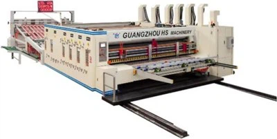
Model:1400x2800

Tech parameters
| Data/model | 900x2000 | 900x2400 | 1200x24000 | 1200x2800 | 1400x2400 | 1400x2800 | 1600x2800 | 1600x3200 | 1600x3600 |
| Max machine speed(pcs/min) | 300 | 300 | 250 | 220 | 220 | 200 | 200 | 180 | 120 |
| Max feeding size(mm) | 880x2000 | 880x2400 | 1180x2400 | 1180x2800 | 1380x2400 | 1380x2800 | 1570x2800 | 1570x3200 | 1570x3600 |
| Min feeding size(mm) | 280x660 | 280x660 | 320x680 | 320x680 | 360x680 | 360x680 | 420x710 | 420x710 | 420x710 |
| Skip feeding(mm) | 1100x2000 | 1100x2400 | 1500x2400 | 1500x2800 | 1700x2400 | 1700x2800 | 1900x2800 | 1900x3200 | 1900x3600 |
| Max printing area(mm) | 850x2000 | 850x2400 | 1150x2400 | 1150x2800 | 1350x2400 | 1350x2800 | 1540x2800 | 1540x3200 | 1540x3600 |
| Thickness of printing plate(mm) | 7.2 | 7.2 | 7.2 | 7.2 | 7.2 | 7.2 | 7.2 | 7.2 | 7.2 |
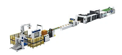
Speed difference compensation device for Carton box manufacturing plant
Regarding the correct use of the speed difference compensation mechanism on VRIDA series die-cutting machines:
When the die-cutting pad wears down, its diameter inevitably decreases, causing a discrepancy in the linear velocity of the surface contact between the cutter roller and the pad roller, resulting in changes in the die-cutting dimensions. The essence of speed difference compensation is to ensure that the linear velocities of the upper and lower rollers are consistent.
The compensation principle of the "precision setting compensation mechanism" is to use an encoder to track the speed of the die-cutting roller, outputting a signal to a variable frequency motor. The variable frequency motor outputs power to a specially designed planetary speed change mechanism, thereby changing the operating speed of the pad roller and achieving synchronization with the die-cutting roller speed. The maximum range is ±1% of the entire die-cutting blade circumference. For example, if the length of the arc blade is 400 mm, then when NO.1 (section D, first segment) is selected, the actual die-cutting dimension is approximately 396 mm. If NO.7 (section 7) is selected, the actual die-cutting dimension is approximately 404 mm. However, if the middle section (NO.4) is selected, the actual die-cutting dimension remains 400 mm.
If it's a new machine or the rubber pads haven't worn out, the customer's die-cutting plate is made according to the drawings of the die-cutting roller we provided. (It must be ensured that the calculation during plate making is based on the arc length of the steel wire, not the arc length of the cutting roller, and the circumferential dimensions of the steel wire are consistent with the actual dimensions.)
By modifying the compensation coefficient on the touchscreen (as seen in the right half of the image below), the compensation value can also be altered. You can adjust the compensation range for each segment by clicking here, but the correction value must fall between two segments; that is, it cannot be higher than the preset parameter of the subsequent segment or lower than the preset parameter of the preceding segment.
1.200, 2.400, and 3.600 really change the inverter's frequency if you wish to modify the die-cutting settings, as seen in the image below. For instance, the inverter parameter in the first segment is 3.600, and the corresponding frequency at a machine speed of 250 is roughly 120 Hz. You must adjust the corresponding parameter if the die-cutting size in this segment is less than the drawing size but the second segment is larger than the real size. The adjustment will not work if it is not set to 2.4 < X < 3.6. You are forced to change the mold size if the size is still too big at 3.6. Operators should be very mindful of this.
Hot Tags: carton box manufacturing plant, China carton box manufacturing plant manufacturers, suppliers, factory